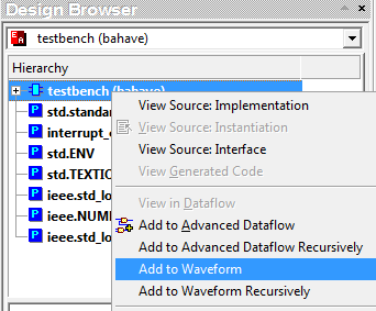
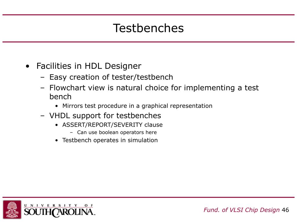
Hdl Designer Testbench
Only after this can we move on to the next step in the chip design workflow.
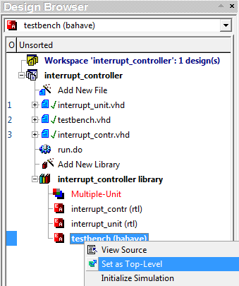
Hdl designer testbench. A lot of people wonder about the difference between rtl and hdl. Also conversion of myhdl testbench to hdl testbench is discussed. The blocks field lists all of the available blocks within the design. Testbench consist of entity without any io ports design instantiated as component clock input and.
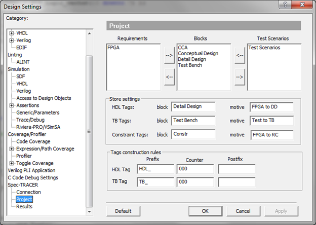
Submit your solution in pdf format. In the category spec tracer project users can configure how hdl and testbench tags in active hdl will be stored in spec tracer. Design 2 1 mux verilog hardware description language along with testbench. Active hdl gui design settings.
Prerequisite multiplexers in digital logic problem. O the fixed point optimization script for data type optimization. Testbench in this chapter we write the testbench for the listing 2 1. A multiplexer is a combinational type of digital circuits that are used to transfer one of the available input lines to the single output and which input has to be transferred to the output it will be decided by the value of the select line signal.
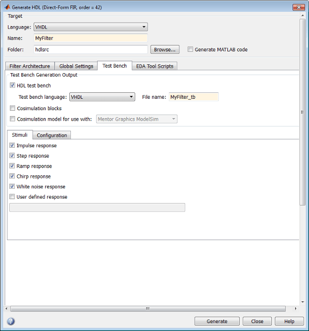
To summarize we first design the circuit using hdl then we verify it using a testbench. A test bench is hdl code that allows you to provide a documented repeatable set of stimuli that is portable across different simulators. Your submission should allow the grader to verify your design by simply running the simulink testbench. Users will need to select the block in which the fpga requirements are stored.


